| |
|

|
|
|
|
|
|
|
|
|
|
|
|
|
|
|
|
|
|
|
|
| |
|
Nozzle
Neck (Thickness and Reinforcement)
|
| |
|
| |
|
ASME BPVC
VIII-1-2015, UG-45 Nozzle Neck
Thickness and,
|
| |
|
UG-37
Reinforcement Required for Openings in Shells and Formed Heads
|
|
|
|
| |
|
|
|
|
|
|
|
|
|
|
|
|
|
|
|
|
|
|
|
|
|
| |
|
|
|
|
|
|
|
|
|
|
(Enter values in yellow cells for calculations and
in blue cells as information)
|
| |
|
ASME BPVC
VIII-1-2015, UG-45 Nozzle Neck
Thickness and,
|
|
|
|
|
|
|
|
|
|
|
|
Page
|
|
|
|
UG-37 Reinforcement
Required for Openings in Shells and Formed Heads
|
|
|
|
|
|
|
|
|
|
|
|
|
|
|
|
|
|
|
|
|
|
|
|
|
|
|
|
|
|
|
|
|
|
|
|
|
|
|
|
|
|
|
|
|
|
|
|
|
|
|
|
|
|
|
|
|
|
|
Introduction
|
|
|
|
|
|
|
|
|
|
|
|
|
|
|
|
|
|
| |
|
|
The
following calculation for minimum internally corroded radial nozzle neck
thickness and reinforcement is based on ASME VIII, Div 1, sections UG-37 and
UG-45. Data Input shall be in Page 2.
|
|
|
|
|
|
|
|
|
|
|
|
|
|
|
|
|
|
|
|
|
|
|
|
|
|
|
|
|
|
|
Pictures / Sketch
|
|
|
|
|
|
|
|
|
|
|
|
|
|
|
|
|
|
|
|
|
|
|
|
|
|
|
|
|
|
|
|
|
|
|
|
|
|
|
|
|
|
|
|
|
|
|
|
|
|
|
|
|
|
|
|
|
|
|
|
|
|
|
|
|
|
|
|
|
|
|
|
|
|
|
|
|
|
|
|
|
|
|
|
|
|
|
|
|
|
|
|
|
|
|
|
|
|
|
|
|
|
|
|
|
|
|
|
|
|
|
|
|
|
|
|
|
|
|
|
|
|
|
|
|
|
|
|
|
|
|
|
|
|
|
|
|
|
|
|
|
|
|
|
|
|
|
|
|
|
|
|
|
|
|
|
|
|
|
|
|
|
|
|
|
|
|
|
|
|
|
|
|
|
|
|
|
|
|
|
|
|
|
|
|
|
|
|
|
|
|
|
|
|
|
|
|
|
|
|
|
|
|
|
|
|
|
|
|
|
|
|
|
|
|
|
|
|
|
|
|
|
|
|
|
|
|
|
|
|
|
|
|
|
|
|
|
|
|
|
|
|
|
|
|
|
|
|
|
|
|
|
|
|
|
|
|
|
|
|
|
|
|
|
|
|
|
|
|
|
|
|
|
|
|
|
|
|
|
|
|
|
|
|
|
|
|
|
|
|
|
|
|
|
|
|
|
|
|
|
|
|
|
|
|
|
|
|
|
|
|
|
|
|
|
|
|
|
|
|
|
|
|
|
|
|
|
|
|
|
|
|
|
|
|
|
|
|
|
|
|
|
|
|
|
|
|
|
|
|
|
|
|
|
|
|
|
|
|
|
|
|
|
|
|
|
|
|
|
|
|
|
|
|
|
|
|
|
|
|
|
|
|
|
|
|
|
|
|
|
|
|
|
|
|
|
|
|
|
|
|
|
|
|
|
|
|
|
|
|
|
|
|
|
|
|
|
|
|
|
|
|
|
|
|
|
|
|
|
|
|
|
|
|
|
|
|
|
|
|
|
|
|
|
|
|
|
|
|
|
|
|
|
|
|
|
|
|
|
|
|
|
|
|
|
|
|
|
|
|
|
|
|
|
|
|
|
|
|
|
|
|
|
|
|
|
|
|
|
|
|
|
|
|
|
|
|
|
|
|
|
|
|
|
|
|
|
|
|
|
|
|
|
|
|
|
|
|
|
|
|
|
|
|
|
|
|
|
|
|
|
|
|
|
|
|
|
|
|
|
|
|
|
|
|
|
|
|
|
|
|
|
|
|
|
|
|
|
|
|
|
|
|
|
|
|
|
|
|
|
|
|
|
|
|
|
|
|
|
|
|
|
|
|
|
|
|
|
|
|
|
|
|
|
|
|
|
|
|
|
|
|
|
|
|
|
|
|
|
|
|
|
|
|
|
|
|
|
|
|
|
|
|
|
|
|
|
|
|
|
|
|
|
|
|
|
|
|
|
|
|
|
|
|
|
|
|
|
|
|
|
|
|
|
|
|
|
|
|
|
|
|
|
|
|
Nozzle size (NPS):
|
|
|
|
|
|
|
|
|
|
|
|
|
|
|
mm
|
|
|
|
|
|
Outside diameter of
reinforcing element, Dp:
|
|
|
|
|
|
|
|
|
|
|
|
mm
|
|
|
|
|
|
|
|
|
|
|
|
|
|
|
|
|
|
|
|
|
|
|
|
|
|
|
|
Summary
|
|
|
|
|
|
|
|
|
|
|
|
|
|
|
|
|
|
|
|
|
Nozzle welded on
|
|
|
|
|
|
|
|
|
|
|
|
|
|
|
|
|
|
|
|
Type of Head (If nozzle
is welded on Head)
|
|
|
|
|
|
|
|
|
|
|
|
|
|
|
|
|
Maximum Limit of
Reinforcement (Parallel to vessel wall)
|
|
|
|
|
|
|
|
|
|
|
mm
|
|
|
|
|
|
Maximum Limit of
Reinforcement (Normal to vessel wall outside)
|
|
|
|
|
|
|
|
|
|
mm
|
|
|
|
|
|
Maximum Limit of
Reinforcement (Normal to vessel wall inside)
|
|
|
|
|
|
|
|
|
|
mm
|
|
|
| |
|
|
Shell or Head Nominal
Thickness, ts or
th
|
|
|
|
|
|
|
|
|
|
|
|
|
mm
|
|
|
| |
|
|
The minimum nozzle
reinforcing pad thickness, te:
|
|
|
|
|
|
|
|
|
|
|
|
mm
|
|
|
|
|
|
The minimum required
nozzle neck thickness, as per UG-45: (For access openings and openings used
only for inspection)
|
|
|
|
mm
|
|
|
|
|
|
The minimum required
nozzle neck thickness, as per UG-45: (For other nozzles)
|
|
|
|
|
|
|
|
mm
|
|
|
| |
|
|
The Nozzle Nominal
thickness, tsn:
|
|
|
|
|
|
|
|
|
|
|
|
|
mm
|
|
|
| |
|
|
Nozzle for:
|
|
|
|
|
|
|
|
|
|
|
|
|
|
|
|
| |
|
|
|
|
|
|
|
|
|
|
|
|
|
|
|
|
|
|
|
|
|
|
|
|
|
|
|
|
|
|
|
Check If tr ≤ t
|
|
|
|
|
|
|
|
|
|
|
|
|
|
|
|
|
|
|
|
Check If trn ≤ tn
|
|
|
|
|
|
|
|
Without reinforcing
element
|
|
|
|
|
|
|
|
|
|
|
|
|
|
|
|
|
|
|
|
Is the available reinforcing area of At greater than the required area of A:
|
|
|
|
|
|
|
|
|
|
|
|
|
|
|
|
|
|
|
|
|
|
|
|
|
|
|
|
|
|
|
|
|
|
|
|
|
|
|
|
|
|
|
|
|
|
|
|
With reinforcing element
added
|
|
|
|
|
|
|
|
|
|
|
|
|
|
|
|
|
| |
|
|
Is the available reinforcing area of At greater than the required area of A:
|
|
|
|
|
|
|
|
|
|
|
|
|
|
|
|
|
|
|
|
|
|
|
|
|
|
|
|
|
|
|
|
|
|
|
|
|
|
|
|
|
|
|
|
|
|
|
ASME BPVC
VIII-1-2015, UG-45 Nozzle Neck
Thickness and,
|
|
|
|
|
|
|
|
|
|
|
|
Page
|
|
|
|
UG-37 Reinforcement
Required for Openings in Shells and Formed Heads
|
|
|
|
|
|
|
|
|
|
|
|
|
|
|
|
|
|
|
|
|
|
|
|
|
|
|
|
|
|
|
|
|
|
|
|
|
|
|
|
|
|
|
|
|
|
|
|
|
|
|
|
|
|
|
|
|
|
|
Formula Data
|
|
|
|
|
|
|
|
Notes
|
|
|
|
|
|
|
|
|
|
|
|
|
|
|
|
|
|
|
|
|
|
|
|
|
|
|
|
|
|
|
|
|
|
|
CA =
|
|
mm
|
|
|
|
|
|
Corrosion Allowance
|
|
|
|
|
|
|
|
|
|
|
U1 =
|
|
|
default value = 0
|
|
|
|
Shell Undertolerance
Allowance (As per UG-16(c) & UG-16(d))
|
|
|
|
|
|
|
U2 =
|
|
mm
|
|
|
|
|
|
Shell Undertolerance
Thickness
|
|
|
|
|
|
|
|
|
|
D =
|
|
mm
|
|
|
|
|
|
Shell Nominal inside Dia
|
|
|
|
|
|
|
|
|
|
|
Do =
|
|
mm
|
|
|
|
|
|
Shell Outside Dia.
|
|
|
|
|
|
|
|
| |
|
|
DH
=
|
|
mm
|
|
|
|
|
|
Head Nominal inside Dia
|
|
|
|
|
|
|
|
| |
|
|
DEH
=
|
|
mm
|
|
|
|
|
|
Ellipsoidal Head inside
Dia. with corrosion removed
|
|
|
|
|
| |
|
|
LTH
=
|
|
mm
|
|
|
|
|
|
Torispherical Head inner
diameter of the skirt adjusted for corrosion
|
|
|
|
|
|
|
d =
|
|
mm
|
(opening in Parent
Material)
|
|
|
Finished diameter of
circular opening
|
|
|
|
|
|
|
|
|
E =
|
|
|
|
|
|
|
|
Assuming E = 1.0
|
|
|
|
|
|
|
|
| |
|
|
E1
=
|
|
|
|
|
|
|
|
|
|
|
|
|
|
|
|
|
|
|
|
|
F =
|
|
|
|
|
|
|
|
1.00
shall be used for all conf. except that Fig. UG-37 may be used for integrally
reinforced openings
|
| |
|
|
fr
=
|
|
|
|
|
|
|
|
Sn/Sv
|
|
|
|
|
|
|
|
|
|
| |
|
|
fr1
=
|
|
|
|
|
|
|
|
Sn/Sv for nozzle wall
inserted through the vessel wall
|
|
|
|
|
| |
|
|
fr2
=
|
|
|
|
|
|
|
|
Sn/Sv
|
|
|
|
|
|
|
|
|
|
| |
|
|
fr3
=
|
|
|
|
|
|
|
|
(lesser of Sn or Sp) / Sv
|
|
|
|
|
|
|
|
| |
|
|
fr4
=
|
|
|
|
|
|
|
|
Sp/Sv
|
|
|
|
|
|
|
|
|
|
|
|
|
h =
|
|
mm
|
default value = 0
|
|
|
|
Nozzle inside projection
|
|
|
|
|
|
|
|
| |
|
|
hH
=
|
|
mm
|
If DH > 0
|
For Nozzle welded on
Ellipsoidal Head 2:1. hH= DH/4
|
|
|
mm
|
|
| |
|
|
K =
|
|
|
|
|
|
|
|
Factor in the equations
for ellipsoidal heads, Table 1-4.1
|
|
|
|
|
| |
|
|
K1
=
|
|
|
|
|
|
|
|
Spherical radius factor
(see Table UG-37)
|
|
|
|
|
|
| |
|
|
LEH
=
|
|
mm
|
|
|
|
|
|
Inside spherical or
crown radius for ellipsoidal head, L = k1D
|
|
|
|
|
|
|
M =
|
|
|
|
|
|
|
|
Assuming M = 1.0
|
|
|
|
|
|
|
|
|
|
|
L =
|
0
|
|
|
|
|
|
|
Applicable for LWNF
only, Figure UG-40 sketch (e)
|
|
|
|
|
|
|
|
P =
|
|
bar
|
|
|
|
|
|
|
|
|
|
|
|
|
|
|
| |
|
|
Pe
=
|
|
bar
|
default value = 0
|
|
|
|
|
|
|
|
|
|
|
|
|
|
| |
|
|
R =
|
|
mm
|
|
|
|
|
|
Shell Inner radius
|
|
|
|
|
|
|
|
|
| |
|
|
Rv
=
|
|
mm
|
|
|
|
|
|
Shell Inner radius with
corrosion & undertolerance removed
|
|
|
|
|
| |
|
|
Rn
=
|
|
mm
|
|
|
|
|
|
Nozzle Inner radius with
corrosion & undertolerance removed
|
|
|
|
| |
|
|
LHH
=
|
|
mm
|
|
|
|
|
|
Hemispherical Head
inside spherical or crown radius adjusted for corrosion
|
|
|
| |
|
|
|
|
|
|
|
|
|
|
|
|
|
|
|
|
|
|
|
|
|
| |
|
|
Sn
=
|
|
MPa
|
Material Specification as per ASME II-D Tables
|
|
|
|
|
|
|
|
|
| |
|
|
Sp
=
|
|
MPa
|
|
|
|
|
|
|
|
|
| |
|
|
Sv
=
|
|
MPa
|
|
|
|
|
|
|
|
|
| |
|
|
T =
|
|
°C
|
|
|
|
|
|
|
|
|
|
|
|
|
|
|
|
| |
|
|
ts
=
|
|
mm
|
Shell Nominal Thk.
|
|
|
Nozzle welded on:
|
|
|
|
|
|
|
| |
|
|
t =
|
|
mm
|
Shell Nom. Thk. adjusted
by Tolerances
|
Head Type:
|
|
|
If Nozzle is welded on
Head
|
|
|
| |
|
|
th
=
|
|
mm
|
Head Nominal Thk. After
forming
|
|
Nozzle for:
|
|
|
|
|
|
|
|
| |
|
|
t =
|
|
mm
|
Head Nominal Thk. After
forming adjusted by tolerances
|
|
|
|
|
|
|
|
|
| |
|
|
t =
|
|
mm
|
Selected t
|
|
|
|
|
|
|
|
|
|
|
|
|
|
|
| |
|
|
ti
=
|
|
mm
|
Nozzle Inside Proj. Thk.
|
|
|
|
|
|
|
|
|
|
|
|
|
| |
|
|
tsn
=
|
|
mm
|
Nozzle Nominal Thk.
|
|
|
|
|
|
|
|
|
|
|
|
|
| |
|
|
tn
=
|
|
mm
|
Nozzle Nominal Thk.
adjusted by tolerances
|
|
|
|
|
|
|
|
|
|
|
| |
|
|
trs
=
|
|
mm
|
|
|
|
|
|
|
|
|
|
|
|
|
|
|
|
| |
|
|
tre
=
|
|
mm
|
|
|
|
|
|
|
|
|
|
|
|
|
|
|
|
| |
|
|
trh
=
|
|
mm
|
|
|
|
|
|
|
|
|
|
|
|
|
|
|
|
| |
|
|
trt
=
|
|
mm
|
|
|
|
|
|
|
|
|
|
|
|
|
|
|
|
| |
|
|
tr
=
|
|
mm
|
Selected tr
|
|
|
|
|
|
|
|
|
|
|
|
|
|
|
|
|
trn
=
|
|
mm
|
|
|
|
|
|
|
|
|
|
|
|
|
|
|
|
|
|
|
|
|
|
|
|
|
|
|
|
|
|
|
|
|
|
|
|
|
|
|
|
Check If tr ≤ t
|
|
|
|
|
|
|
|
|
|
|
|
|
|
|
|
|
|
| |
|
|
|
|
|
|
|
|
|
|
|
|
|
|
|
|
|
|
|
|
|
| |
|
|
A41
leg =
|
|
mm
|
|
|
|
|
|
|
|
|
|
|
|
|
|
|
|
| |
|
|
A43
leg =
|
|
mm
|
|
|
|
|
|
|
|
|
|
|
|
|
|
|
|
| |
|
|
|
|
|
|
|
|
|
|
|
|
|
|
|
|
|
|
|
|
|
| |
|
|
|
|
|
|
|
|
|
|
|
|
|
|
|
|
|
|
|
|
| |
|
|
Nozzle Neck dimensions
(ASME B36.10M & ASME B36.19M):
|
|
|
|
|
|
|
|
|
|
|
|
|
|
|
|
|
|
|
|
|
|
|
|
|
|
|
|
|
|
|
|
|
|
|
|
|
|
Pipe size (DN):
|
|
|
|
|
|
|
|
Nozzle Neck Nominal
thickness, tsn:
|
|
|
mm
|
|
|
|
|
Schedule:
|
|
|
|
|
|
|
|
Nozzle Neck thickness
undertolerance, U3:
|
|
mm
|
|
|
|
|
Approximate ID:
|
|
|
mm
|
|
|
|
|
(undertolerance = 12.5%)
|
|
|
|
|
|
|
|
|
|
Approximate OD:
|
|
|
mm
|
|
|
|
|
Nominal thickness less
'c' & 'U3', tn:
|
|
|
mm
|
|
|
|
|
|
|
|
|
|
|
|
|
|
|
|
|
|
|
|
|
|
|
|
|
|
|
|
Check If trn ≤ tn
|
|
|
|
|
|
|
|
|
|
|
|
|
|
|
|
|
|
|
|
|
|
|
|
|
|
|
|
|
|
|
|
|
|
|
|
|
|
|
|
|
Nozzle Neck thickness trn for external
pressure as per Section VIII Div 1 - UG 28(c)
|
|
|
|
|
|
|
|
|
|
| |
|
|
trn for external pressure:
|
|
mm
|
default value = 0
|
|
|
|
|
|
|
|
|
|
|
|
|
|
|
|
|
|
|
|
|
|
|
|
|
|
|
|
|
|
|
|
|
|
|
|
|
Nozzle Pad details
|
|
|
|
|
|
|
|
|
|
|
|
|
|
|
|
|
|
| |
|
|
Dp
=
|
|
mm
|
|
|
|
|
|
|
|
|
|
|
|
|
|
| |
|
|
te
=
|
|
mm
|
|
|
|
|
|
|
|
|
|
|
|
|
|
|
|
| |
|
|
A42
leg =
|
|
mm
|
default value = 0
|
|
|
|
|
|
|
|
|
|
|
|
|
|
|
|
|
|
|
|
|
|
|
|
|
|
|
|
|
|
|
|
|
|
|
|
|
|
|
|
|
|
|
|
|
|
|
|
|
|
|
|
|
|
|
|
|
|
|
|
|
|
|
|
|
|
|
|
|
|
|
|
|
|
|
|
|
|
|
|
|
|
ASME BPVC
VIII-1-2015, UG-45 Nozzle Neck
Thickness and,
|
|
|
|
|
|
|
|
|
|
|
|
Page
|
|
|
|
UG-37 Reinforcement
Required for Openings in Shells and Formed Heads
|
|
|
|
|
|
|
|
|
|
|
|
|
|
|
|
|
|
|
|
|
|
|
|
|
|
|
|
|
|
|
|
|
|
| |
|
|
|
|
|
|
|
|
|
|
|
|
|
|
|
|
|
|
|
|
|
| |
|
|
Calculations
|
|
|
|
|
|
|
|
|
|
|
ASME VIII Reference
|
|
|
|
|
| |
|
|
|
|
|
|
|
|
|
|
|
|
|
|
|
|
|
|
|
|
|
| |
|
|
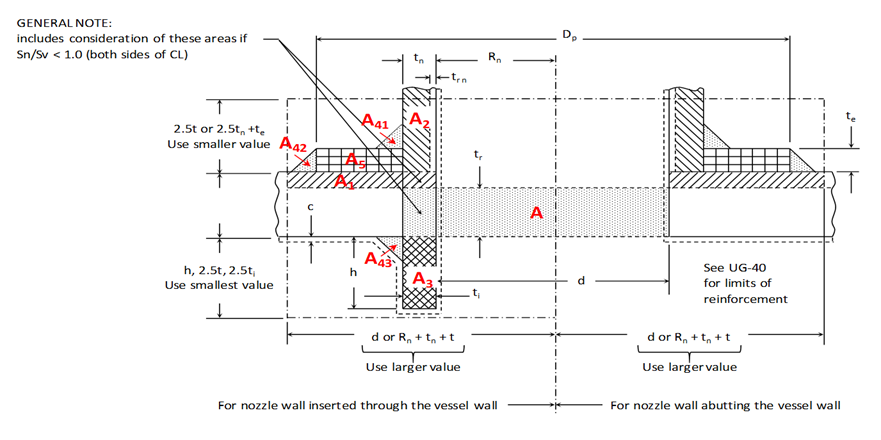
(a) Calculate limits of
reinforcement
|
|
|
|
|
|
|
|
|
|
|
|
|
|
|
|
| |
|
|
|
|
|
|
|
|
|
|
|
|
|
|
|
|
|
|
|
|
|
| |
|
|
Parallel to vessel wall,
use larger of :
|
|
|
|
|
|
|
|
|
UG-40
|
|
|
|
|
|
|
| |
|
|
|
|
|
|
|
|
|
|
|
|
|
|
|
|
|
|
|
|
|
| |
|
|
d =
|
|
|
mm
|
|
|
|
|
|
|
|
UG-40(b)(1)
|
|
|
|
|
|
| |
|
|
|
|
|
|
|
|
|
|
|
|
|
|
|
|
|
|
|
|
|
| |
|
|
Rn + tn
+ t =
|
|
mm
|
|
|
|
|
|
|
|
UG-40(b)(2)
|
|
|
|
|
|
| |
|
|
|
|
|
|
|
|
|
|
|
|
|
|
|
|
|
|
|
|
|
| |
|
|
Use
|
|
|
mm
|
|
|
|
|
|
|
|
|
|
|
|
|
|
|
| |
|
|
|
|
|
|
|
|
|
|
|
|
|
|
|
|
|
|
|
|
|
| |
|
|
Normal to vessel wall
outside use smaller of:
|
|
|
|
|
|
|
|
|
|
|
|
|
|
|
| |
|
|
|
|
|
|
|
|
|
|
|
|
|
|
|
|
|
|
|
|
|
| |
|
|
2.5t =
|
|
|
mm
|
|
|
|
|
|
|
|
UG-40(c)(1)
|
|
|
|
|
|
| |
|
|
|
|
|
|
|
|
|
|
|
|
|
|
|
|
|
|
|
|
|
| |
|
|
2.5tn + te =
|
|
mm
|
|
|
|
|
|
|
|
UG-40(c)(2)
|
|
|
|
|
|
| |
|
|
|
|
|
|
|
|
|
|
|
|
|
|
|
|
|
|
|
|
|
| |
|
|
Use
|
|
|
mm
|
|
|
|
|
|
|
|
|
|
|
|
|
|
|
| |
|
|
|
|
|
|
|
|
|
|
|
|
|
|
|
|
|
|
|
|
|
| |
|
|
Normal to vessel wall
inside use smaller of:
|
|
|
|
|
|
|
|
|
|
|
|
|
|
|
| |
|
|
|
|
|
|
|
|
|
|
|
|
|
|
|
|
|
|
|
|
|
| |
|
|
h =
|
|
|
mm
|
|
|
|
|
|
|
|
UG-40(c)(1)
|
|
|
|
|
|
| |
|
|
|
|
|
|
|
|
|
|
|
|
|
|
|
|
|
|
|
|
|
| |
|
|
2.5t =
|
|
|
mm
|
|
|
|
|
|
|
|
UG-40(c)(2)
|
|
|
|
|
|
| |
|
|
|
|
|
|
|
|
|
|
|
|
|
|
|
|
|
|
|
|
|
| |
|
|
2.5ti =
|
|
|
mm
|
|
|
|
|
|
|
|
UG-40(c)(2)
|
|
|
|
|
|
| |
|
|
|
|
|
|
|
|
|
|
|
|
|
|
|
|
|
|
|
|
|
| |
|
|
Use
|
|
|
mm
|
|
|
|
|
|
|
|
|
|
|
|
|
|
|
| |
|
|
|
|
|
|
|
|
|
|
|
|
|
|
|
|
|
|
|
|
|
| |
|
|
(b) Shell, Head and
nozzle required thickness:
|
|
|
|
|
|
|
|
|
|
|
|
|
|
|
| |
|
|
|
|
|
|
|
|
|
|
|
|
|
|
|
|
|
|
|
|
|
| |
|
|
with
|
|
|
|
|
|
|
|
|
|
|
|
|
|
|
|
|
|
|
| |
|
|
CA =
|
|
mm
|
|
|
|
|
|
|
|
|
|
|
|
|
|
|
|
| |
|
|
P =
|
|
bar
|
|
|
|
|
|
|
|
|
|
|
|
|
|
|
|
| |
|
|
Pe
=
|
|
bar
|
|
|
|
|
|
|
|
|
|
|
|
|
|
|
|
| |
|
|
DEH
=
|
|
mm
|
|
|
|
|
|
|
|
|
|
|
|
|
|
|
|
| |
|
|
LTH =
|
|
mm
|
|
|
|
|
|
|
|
|
|
|
|
|
|
|
|
| |
|
|
RV
=
|
|
mm
|
|
|
|
|
|
|
|
|
|
|
|
|
|
|
|
| |
|
|
LHH =
|
|
mm
|
|
|
|
|
|
|
|
|
|
|
|
|
|
|
|
| |
|
|
Rn
=
|
|
mm
|
|
|
|
|
|
|
|
|
|
|
|
|
|
|
|
| |
|
|
Sv
=
|
|
MPa
|
|
|
|
|
|
|
|
|
|
|
|
|
|
|
|
| |
|
|
Sn
=
|
|
MPa
|
|
|
|
|
|
|
|
|
|
|
|
|
|
|
|
| |
|
|
E =
|
|
|
|
|
|
|
|
|
|
|
|
|
|
|
|
|
|
| |
|
|
K =
|
|
|
|
|
|
|
|
|
|
|
|
|
|
|
|
|
|
| |
|
|
M =
|
|
|
|
|
|
|
|
|
|
|
|
|
|
|
|
|
|
| |
|
|
|
|
|
|
|
|
|
|
|
|
|
|
|
|
|
|
|
|
|
| |
|
|
Required shell
thickness:
|
|
(Internal Pressure)
|
|
|
|
|
|
|
Required shell
thickness:
|
|
(External
Pressure)
|
| |
|
|
|
|
|
|
|
|
|
|
|
|
|
|
|
|
|
|
|
|
|
| |
|
|
trs =
|
PRv
|
+ CA
|
|
|
|
|
|
|
|
|
|
trs =
|
PRv
|
+ CA
|
|
|
|
|
| |
|
|
SE - 0.6P
|
|
|
|
|
|
|
|
|
|
SE - 0.6P
|
|
|
|
|
| |
|
|
trs
=
|
|
mm
|
|
|
|
|
|
|
|
|
trs
=
|
|
mm
|
|
|
|
| |
|
|
|
|
|
|
|
|
|
|
|
|
|
|
|
|
|
|
|
|
|
| |
|
|
|
|
|
|
|
|
|
|
|
|
|
|
|
|
|
|
|
|
|
| |
|
|
Required ellipsoidal
head thickness:
|
(Internal Pressure)
|
|
|
|
|
|
|
Required ellipsoidal
head thickness:
|
(External
Pressure)
|
| |
|
|
|
|
|
|
|
|
|
|
|
|
|
|
|
|
|
|
|
|
|
| |
|
|
tre =
|
PDEHK
|
+ CA
|
|
|
|
|
|
|
|
|
|
tre =
|
PDEHK
|
+ CA
|
|
|
|
|
| |
|
|
2SE - 0.2P
|
|
|
|
|
|
|
|
|
|
2SE - 0.2P
|
|
|
|
|
| |
|
|
tre
=
|
|
mm
|
|
|
|
|
|
|
|
|
tre
=
|
|
mm
|
|
|
|
| |
|
|
|
|
|
|
|
|
|
|
|
|
|
|
|
|
|
|
|
|
|
| |
|
|
|
|
|
|
|
|
|
|
|
|
|
|
|
|
|
|
|
|
|
| |
|
|
Required hemispherical
head thickness:
|
(Internal Pressure)
|
|
|
|
|
|
|
Required hemispherical
head thickness:
|
(External
Pressure)
|
| |
|
|
|
|
|
|
|
|
|
|
|
|
|
|
|
|
|
|
|
|
|
| |
|
|
trh =
|
PLHH
|
+ CA
|
|
|
|
|
|
|
|
|
|
trh =
|
PLHH
|
+ CA
|
|
|
|
|
| |
|
|
2SE - 0.2P
|
|
|
|
|
|
|
|
|
|
2SE - 0.2P
|
|
|
|
|
| |
|
|
trh
=
|
|
mm
|
|
|
|
|
|
|
|
|
trh
=
|
|
mm
|
|
|
|
| |
|
|
|
|
|
|
|
|
|
|
|
|
|
|
|
|
|
|
|
|
|
| |
|
|
|
|
|
|
|
|
|
|
|
|
|
|
|
|
|
|
|
|
|
| |
|
|
Required torispherical
head thickness:
|
(Internal Pressure)
|
|
|
|
|
|
|
Required torispherical
head thickness:
|
(External
Pressure)
|
| |
|
|
|
|
|
|
|
|
|
|
|
|
|
|
|
|
|
|
|
|
|
| |
|
|
trt =
|
PLTHM
|
+ CA
|
|
|
|
|
|
|
|
|
|
trt =
|
PLTHM
|
+ CA
|
|
|
|
|
| |
|
|
2SE - 0.2P
|
|
|
|
|
|
|
|
|
|
2SE - 0.2P
|
|
|
|
|
| |
|
|
trt
=
|
|
mm
|
|
|
|
|
|
|
|
|
trt
=
|
|
mm
|
|
|
|
| |
|
|
|
|
|
|
|
|
|
|
|
|
|
|
|
|
|
|
|
|
|
| |
|
|
|
|
|
|
|
|
|
|
|
|
|
|
|
|
|
|
|
|
|
|
|
|
Required nozzle neck
thickness:
|
(Internal Pressure)
|
|
|
|
|
|
|
Required nozzle neck
thickness:
|
(External
Pressure)
|
|
|
|
|
|
|
|
|
|
|
|
|
|
|
|
As per Section VIII Div
1 - UG 28(c) - Thickness of Shells
|
|
|
|
|
trn =
|
PRn
|
+ CA
|
|
|
|
|
|
|
|
|
|
and Tubes under External
Pressure
|
|
|
|
| |
|
|
SE - 0.6P
|
|
|
|
|
|
|
|
|
|
|
|
|
|
|
|
|
|
|
trn
=
|
|
mm
|
|
|
|
|
|
|
|
|
trn
=
|
|
mm
|
|
|
|
|
|
|
|
|
|
|
|
|
|
|
|
|
|
|
|
|
|
|
|
|
|
|
|
|
|
|
|
|
|
|
|
|
|
|
|
|
|
|
|
|
|
|
|
| |
|
|
|
|
|
|
|
|
|
|
|
|
|
|
|
|
|
|
|
|
|
| |
|
ASME BPVC
VIII-1-2015, UG-45 Nozzle Neck
Thickness and,
|
|
|
|
|
|
|
|
|
|
|
|
Page
|
|
| |
|
UG-37 Reinforcement
Required for Openings in Shells and Formed Heads
|
|
|
|
|
|
|
|
|
|
|
|
| |
|
|
|
|
|
|
|
|
|
|
|
|
|
|
|
|
|
|
|
|
|
| |
|
|
|
|
|
|
|
|
|
|
|
|
|
|
|
|
|
|
|
|
|
| |
|
|
(c) Determine required
replacement area:
|
|
|
|
|
|
|
|
|
Notes
|
|
|
|
|
|
|
| |
|
|
|
|
|
|
|
|
|
|
|
|
|
|
|
|
|
|
|
|
|
| |
|
|
A =
|
d tr
F + 2tn tr F(1 - fr1)
|
|
|
|
|
|
|
|
|
|
Ref: UG-37 (C)- Design
for Internal Pressure.
|
|
|
| |
|
|
|
|
|
|
|
|
|
|
|
|
|
|
|
|
|
|
|
|
|
| |
|
|
A =
|
|
|
mm2
|
|
|
|
|
|
|
|
|
|
|
|
|
|
|
| |
|
|
|
|
|
|
|
|
|
|
|
|
|
|
|
|
|
|
|
|
|
| |
|
|
(d) Calculate area
contributions:
|
|
|
|
|
|
|
|
|
|
|
|
|
|
|
|
|
| |
|
|
|
|
|
|
|
|
|
|
|
|
|
|
|
|
|
|
|
|
|
| |
|
|
Area available in the
vessel wall, use larger value:
|
|
|
|
|
|
|
|
|
|
|
|
|
|
|
| |
|
|
|
|
|
|
|
|
|
|
|
|
|
|
|
|
|
|
|
|
|
| |
|
|
A1.1 =
|
d(E1t - Ftr) - 2tn(E1t - Ftr)(1 - fr1)
|
|
|
|
|
|
|
|
|
|
|
|
|
|
|
| |
|
|
|
|
|
|
|
|
|
|
|
|
|
|
|
|
|
|
|
|
|
| |
|
|
A1.1 =
|
|
|
mm2
|
|
|
|
|
|
|
|
|
|
|
|
|
|
|
| |
|
|
|
|
|
|
|
|
|
|
|
|
|
|
|
|
|
|
|
|
| |
|
|
A1.2 =
|
2(t + tn)(E1t - Ftr) - 2tn(E1t - Ftr)(1 - Fr1)
|
|
|
|
|
|
|
|
|
|
|
|
|
|
|
| |
|
|
|
|
|
|
|
|
|
|
|
|
|
|
|
|
|
|
|
|
| |
|
|
A1.2 =
|
|
|
mm2
|
|
|
|
|
|
|
|
|
|
|
|
|
|
|
| |
|
|
|
|
|
|
|
|
|
|
|
|
|
|
|
|
| |
|
|
Use A1 =
|
|
mm2
|
|
|
|
|
|
|
|
|
|
|
|
|
|
|
| |
|
|
|
|
|
|
|
|
|
|
|
|
|
|
|
|
|
|
| |
|
|
|
|
|
|
|
|
|
|
|
|
|
|
|
|
|
|
|
|
|
| |
|
|
Area available in nozzle
projecting outward, use smaller value:
|
|
|
|
|
|
|
|
|
|
|
|
|
| |
|
|
|
|
|
|
|
|
|
|
|
|
|
|
|
|
|
|
|
|
|
| |
|
|
With reinforcing element
added
|
|
|
|
|
|
|
|
|
|
Without reinforcing
element
|
|
|
|
|
| |
|
|
A2.1 =
|
5(tn - trn)(fr2)(t)
|
|
|
|
|
|
|
|
|
|
A2.1 =
|
5(tn - trn)(fr2)(t)
|
|
|
|
|
| |
|
|
|
|
|
|
|
|
|
|
|
|
|
|
|
|
|
|
|
|
|
| |
|
|
A2.1 =
|
|
|
mm2
|
|
|
|
|
|
|
|
A2.1 =
|
|
|
mm2
|
|
|
| |
|
|
|
|
|
|
|
|
|
|
|
|
|
|
|
|
|
|
|
|
|
| |
|
|
With reinforcing element
added
|
|
|
|
|
|
|
|
|
|
Without reinforcing
element
|
|
|
|
|
| |
|
|
A2.2 =
|
2(tn - trn)(2.5tn + te)(fr2)
|
|
|
|
|
|
|
|
|
A2.2 =
|
5(tn - trn)(fr2)(tn)
|
|
|
|
|
| |
|
|
|
|
|
|
|
|
|
|
|
|
|
|
|
|
|
|
|
|
|
| |
|
|
A2.2 =
|
|
|
mm2
|
|
|
|
|
|
|
|
A2.2 =
|
|
|
mm2
|
|
|
| |
|
|
|
|
|
|
|
|
|
|
|
|
|
|
|
|
|
|
|
|
|
| |
|
|
Use A2 =
|
|
mm2
|
|
|
|
|
|
|
|
Use A2 =
|
|
mm2
|
|
|
| |
|
|
|
|
|
|
|
|
|
|
|
|
|
|
|
|
|
|
|
|
|
| |
|
|
|
|
|
|
|
|
|
|
|
|
|
|
|
|
|
|
|
|
|
| |
|
|
Area available due to
inward projection of nozzle, use smaller value:
|
|
|
|
|
|
|
|
|
|
|
|
|
| |
|
|
|
|
|
|
|
|
|
|
|
|
|
|
|
|
|
|
|
|
|
| |
|
|
A3.1 =
|
5t ti fr2
|
|
|
|
|
|
|
|
|
|
|
|
|
|
|
|
|
|
| |
|
|
|
|
|
|
|
|
|
|
|
|
|
|
|
|
|
|
|
|
|
| |
|
|
A3.1 =
|
|
|
mm2
|
|
|
|
|
|
|
|
|
|
|
|
|
|
|
| |
|
|
|
|
|
|
|
|
|
|
|
|
|
|
|
|
|
|
|
|
|
| |
|
|
A3.2 =
|
5ti
ti fr2
|
|
|
|
|
|
|
|
|
|
|
|
|
|
|
|
|
|
| |
|
|
|
|
|
|
|
|
|
|
|
|
|
|
|
|
|
|
|
|
|
| |
|
|
A3.2 =
|
|
|
mm2
|
|
|
|
|
|
|
|
|
|
|
|
|
|
|
| |
|
|
|
|
|
|
|
|
|
|
|
|
|
|
|
|
|
|
|
|
|
| |
|
|
A3.3 =
|
2h ti fr2
|
|
|
|
|
|
|
|
|
|
|
|
|
|
|
|
|
|
| |
|
|
|
|
|
|
|
|
|
|
|
|
|
|
|
|
|
|
|
|
|
| |
|
|
A3.3 =
|
|
|
mm2
|
|
|
|
|
|
|
|
|
|
|
|
|
|
|
| |
|
|
|
|
|
|
|
|
|
|
|
|
|
|
|
|
|
|
|
|
|
| |
|
|
Use A3 =
|
|
mm2
|
|
|
|
|
|
|
|
|
|
|
|
|
|
|
| |
|
|
|
|
|
|
|
|
|
|
|
|
|
|
|
|
|
|
|
|
|
| |
|
|
|
|
|
|
|
|
|
|
|
|
|
|
|
|
|
|
|
|
|
| |
|
|
|
|
|
|
|
|
|
|
|
|
|
|
|
|
|
|
|
|
|
| |
|
|
|
|
|
|
|
|
|
|
|
|
|
|
|
|
|
|
|
|
|
| |
|
|
|
|
|
|
|
|
|
|
|
|
|
|
|
|
|
|
|
|
|
| |
|
ASME BPVC
VIII-1-2015, UG-45 Nozzle Neck
Thickness and,
|
|
|
|
|
|
|
|
|
|
|
|
Page
|
|
| |
|
UG-37 Reinforcement
Required for Openings in Shells and Formed Heads
|
|
|
|
|
|
|
|
|
|
|
|
| |
|
|
|
|
|
|
|
|
|
|
|
|
|
|
|
|
|
|
|
|
|
| |
|
|
|
|
|
|
|
|
|
|
|
|
|
|
|
|
|
|
|
|
|
| |
|
|
Area available in welds:
|
|
|
|
|
|
|
|
|
|
|
|
|
|
|
|
|
| |
|
|
|
|
|
|
|
|
|
|
|
|
|
|
|
|
|
|
|
|
|
| |
|
|
with reinforcing element
added
|
|
|
|
|
|
|
|
|
|
Without reinforcing
element
|
|
|
|
|
| |
|
|
A41
=
|
(leg)2 fr3
|
|
Outward Nozzle Weld
|
|
|
|
|
|
|
A41
=
|
(leg)2 fr2
|
|
Outward Nozzle Weld
|
|
| |
|
|
|
|
|
|
|
|
|
|
|
|
|
|
|
|
|
|
|
|
|
| |
|
|
A41
=
|
|
|
mm2
|
|
|
|
|
|
|
|
A41
=
|
|
|
mm2
|
|
|
| |
|
|
|
|
|
|
|
|
|
|
|
|
|
|
|
|
|
|
|
|
|
| |
|
|
A42
=
|
(leg)2 fr4
|
|
Outer Element/Pad Weld
|
|
|
|
|
|
|
|
|
|
|
|
|
|
| |
|
|
|
|
|
|
|
|
|
|
|
|
|
|
|
|
|
|
|
|
|
| |
|
|
A42
=
|
|
|
mm2
|
|
|
|
|
|
|
|
|
|
|
|
|
|
| |
|
|
|
|
|
|
|
|
|
|
|
|
|
|
|
|
|
|
|
|
|
| |
|
|
A43
=
|
(leg)2 fr2
|
|
Inward Nozzle Weld
|
|
|
|
|
|
|
A43
=
|
(leg)2 fr2
|
|
Inward Nozzle Weld
|
|
| |
|
|
|
|
|
|
|
|
|
|
|
|
|
|
|
|
|
|
|
|
|
| |
|
|
A43
=
|
|
|
mm2
|
|
|
|
|
|
|
|
A43
=
|
|
|
mm2
|
|
|
| |
|
|
|
|
|
|
|
|
|
|
|
|
|
|
|
|
|
|
|
|
|
| |
|
|
Area in reinforcing pad:
|
|
|
|
|
|
|
|
|
|
|
|
|
|
|
|
|
| |
|
|
|
|
|
|
|
|
|
|
|
|
|
|
|
|
|
|
|
|
|
| |
|
|
A5
=
|
(Dp - d - 2tn)te fr4
|
|
|
|
|
|
|
|
|
|
|
|
|
|
|
|
|
| |
|
|
|
|
|
|
|
|
|
|
|
|
|
|
|
|
|
|
|
|
|
| |
|
|
A5
=
|
|
|
mm2
|
|
|
|
|
|
|
|
|
|
|
|
|
|
|
| |
|
|
|
|
|
|
|
|
|
|
|
|
|
|
|
|
|
|
|
|
|
| |
|
|
(e) Total area
available:
|
|
|
|
|
|
|
|
|
|
|
|
|
|
|
|
|
| |
|
|
|
|
|
|
|
|
|
|
|
|
|
|
|
|
|
|
|
|
|
| |
|
|
With reinforcing element
added
|
|
|
|
|
|
|
|
|
|
Without reinforcing
element
|
|
|
|
|
| |
|
|
At
=
|
A1 + A2 + A3 + A41 + A42 + A43 + A5
|
|
|
|
|
|
|
|
At
=
|
A1 + A2 + A3 + A41 + A43
|
|
|
|
| |
|
|
|
|
|
|
|
|
|
|
|
|
|
|
|
|
|
|
|
|
|
| |
|
|
At
=
|
|
mm2
|
|
|
|
|
|
|
|
|
At
=
|
|
mm2
|
|
|
|
| |
|
|
|
|
|
|
|
|
|
|
|
|
|
|
|
|
|
|
|
|
|
| |
|
|
At
=
|
|
mm2
|
|
|
mm2
|
|
|
(A)
|
|
|
|
At
=
|
|
mm2
|
|
|
mm2
|
(A')
|
| |
|
|
|
|
|
|
|
|
|
|
|
|
|
|
|
|
|
|
|
|
|
| |
|
|
Is the available
reinforcing area of At is
|
|
|
|
|
|
|
|
|
Is the available
reinforcing area of At is
|
|
|
|
| |
|
|
greater than the
required area of A:
|
|
|
|
|
|
|
|
|
greater than the
required area of A:
|
|
|
|
| |
|
|
|
|
|
|
|
| |
|
|
|
|
|
|
|
|
|
|
|
|
|
|
| |
|
|
|
|
|
|
|
|
|
|
|
|
|
|
|
|
|
|
|
|
|
| |
|
|
|
|
|
|
|
|
|
|
|
|
|
|
|
|
|
|
|
|
|
| |
|
|
|
|
|
|
|
|
|
|
|
|
|
|
|
|
|
|
|
|
|
| |
|
|
|
|
|
|
|
|
|
|
|
|
|
|
|
|
|
|
|
|
|
| |
|
|
|
|
|
|
|
|
|
|
|
|
|
|
|
|
|
|
|
|
|
| |
|
ASME BPVC
VIII-1-2015, UG-45 Nozzle Neck
Thickness and,
|
|
|
|
|
|
|
|
|
|
|
|
Page
|
|
| |
|
UG-37 Reinforcement
Required for Openings in Shells and Formed Heads
|
|
|
|
|
|
|
|
|
|
|
|
| |
|
|
|
|
|
|
|
|
|
|
|
|
|
|
|
|
|
|
|
|
|
| |
|
|
|
|
|
|
|
|
|
|
|
|
|
|
|
|
|
|
|
|
|
| |
|
|
(g) Check nozzle neck
thickness as specified in UG-45.
|
|
|
|
|
|
|
|
|
|
|
|
|
|
| |
|
|
|
|
|
|
|
|
|
|
|
|
|
|
|
|
|
|
|
|
|
| |
|
|
For access openings and
openings used only for inspection:
|
|
|
|
|
|
|
|
|
|
|
|
|
|
| |
|
|
|
|
|
|
|
|
|
|
|
|
|
|
|
|
|
|
|
|
|
| |
|
|
tUG-45 = ta
|
|
|
|
|
|
|
|
|
|
|
|
|
|
|
|
|
|
|
| |
|
|
|
|
|
|
|
|
|
|
|
|
|
|
|
|
|
|
|
|
|
| |
|
|
For all nozzles other
than access openings and openings used only for inspection, determine tb:
|
|
|
|
|
|
|
|
|
|
| |
|
|
|
|
|
|
|
|
|
|
|
|
|
|
|
|
|
|
|
|
|
| |
|
|
tb = min[tb3, max(tb1, tb2)]
|
|
|
|
|
|
|
|
|
|
|
|
|
|
|
|
|
| |
|
|
|
|
|
|
|
|
|
|
|
|
|
|
|
|
|
|
|
|
|
| |
|
|
tUG-45 = max(ta, tb)
|
|
|
|
|
|
|
|
|
|
|
|
|
|
|
|
|
|
| |
|
|
|
|
|
|
|
|
|
|
|
|
|
|
|
|
|
|
|
|
|
| |
|
where
|
|
|
|
|
|
|
|
|
|
|
|
|
|
|
|
|
|
|
|
| |
|
ta
=
|
minimum neck
thickness required for internal and external pressure using UG-27 and UG-28
(plus corrosion allowance),
|
|
| |
|
|
as applicable.
|
|
|
|
|
|
|
|
|
|
|
|
|
|
|
|
|
|
| |
|
tb1
=
|
for vessels under
internal pressure, the thickness (plus corrosion allowance) required for
pressure (assuming
|
|
|
|
|
|
|
|
| |
|
|
E = 1.0) for the shell
or head at the location where the nozzle neck or other connection attaches to
the vessel.
|
|
|
|
|
|
|
|
| |
|
tb2
=
|
for vessels under
external pressure, the thickness (plus corrosion allowance) obtained by using
the external
|
|
|
|
|
|
|
|
|
| |
|
|
design pressure as an
equivalent internal design pressure (assuming E = 1.0) in the formula for the
shell or
|
|
|
|
|
|
|
|
|
| |
|
|
head at the location
where the nozzle neck or other connection attaches to the vessel.
|
|
|
|
|
|
|
|
|
|
|
| |
|
tb3
=
|
the thickness given in
Table UG-45 plus the thickness added for corrosion allowance.
|
|
|
|
|
|
|
|
|
|
|
| |
|
tUG-45 =
|
minimum wall thickness
of nozzle necks
|
|
|
|
|
|
|
|
|
|
|
|
|
|
|
|
| |
|
|
|
|
|
|
|
|
|
|
|
|
|
|
|
|
|
|
|
|
|
| |
|
DN =
|
|
|
|
|
mm
|
|
|
|
|
|
|
|
|
|
| |
|
trn
=
|
|
|
|
|
mm
|
|
|
|
|
|
|
|
|
|
|
|
|
|
| |
|
ta
=
|
|
|
|
|
mm
|
|
|
|
|
|
|
trn with corrosion and undertolerance removed
|
|
|
| |
|
tb1
=
|
|
|
|
|
mm
|
|
|
|
|
|
|
tr with corrosion and undertolerance removed
|
|
|
| |
|
tb2
=
|
|
|
|
|
mm
|
|
|
|
|
|
|
|
|
|
|
|
|
|
| |
|
tb3
=
|
|
|
|
|
mm
|
|
|
|
|
|
|
|
|
|
|
|
| |
|
tb
=
|
|
|
|
|
mm
|
|
|
|
|
|
|
|
|
|
|
|
|
|
| |
|
|
|
|
|
|
|
|
|
|
|
|
|
|
|
|
|
|
|
|
|
| |
|
For access openings and
openings used only for inspection:
|
|
|
|
|
|
|
|
|
|
|
|
|
|
| |
|
Minimum Nozzle Neck
Thickness required, tUG-45 = ta
|
|
|
|
|
|
mm
|
|
|
|
|
|
|
|
|
| |
|
|
|
|
|
|
|
|
|
|
|
|
|
|
|
|
|
|
|
|
|
| |
|
For other nozzles:
|
|
|
|
|
|
|
|
|
|
|
|
|
|
|
|
|
|
| |
|
Minimum Nozzle Neck
Thickness required, tUG-45 = max(ta, tb)
|
|
|
|
|
mm
|
|
|
|
|
|
|
|
|
| |
|
|
|
|
|
|
|
|
|
|
|
|
|
|
|
|
|
|
|
|
|
| |
|
Nozzle Neck Nominal
thickness, tsn =
|
|
|
|
|
|
|
|
mm
|
|
|
|
|
|
|
|
|
| |
|
|
|
|
|
|
|
|
|
|
|
|
|
|
|
|
|
|
|
|
|